Development of custom electronic boards with CNC Router.
This week we focus on electronic production using a CNC router. Our first team task was to test and calibrate the machine parameters. Once this stage was completed, we proceeded to perform the necessary tests. Once the board was ready, we proceeded to solder the electronic components and then programmed the XIAO ESP32 C3.
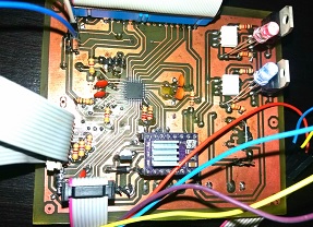
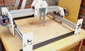
To carry out the tasks assigned this week, I used a home-made CNC machine which will be described below:
We carry out group work at home using a machine manufactured in Peru, specifically in Huánuco. We did it with my colleague Wilber Giron, who resides in the city of Pasco.
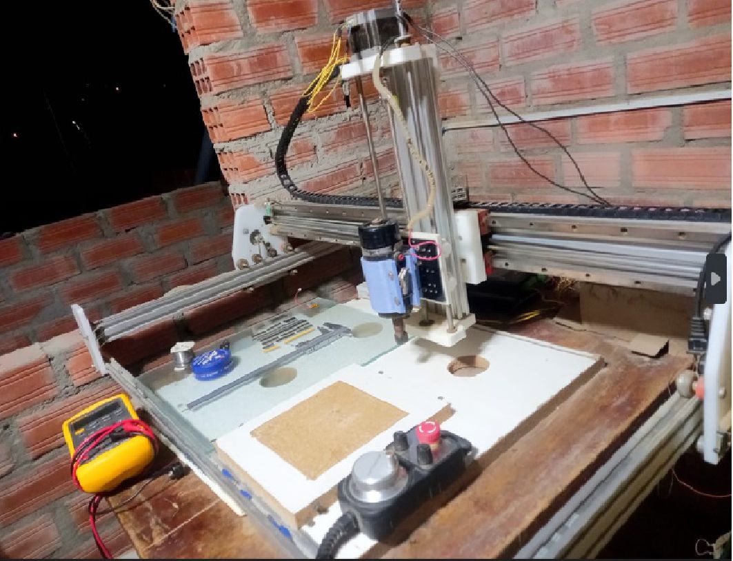
Homemade machine.
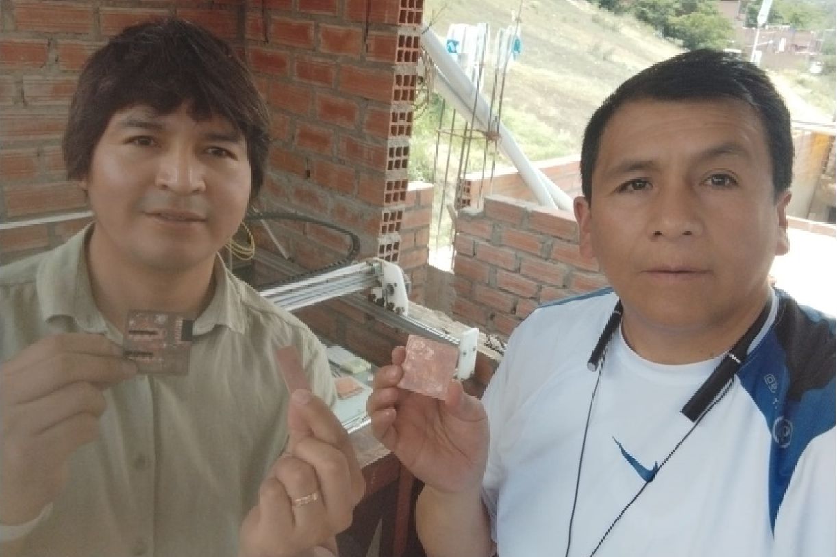
With colleague Wilber from Pasco.
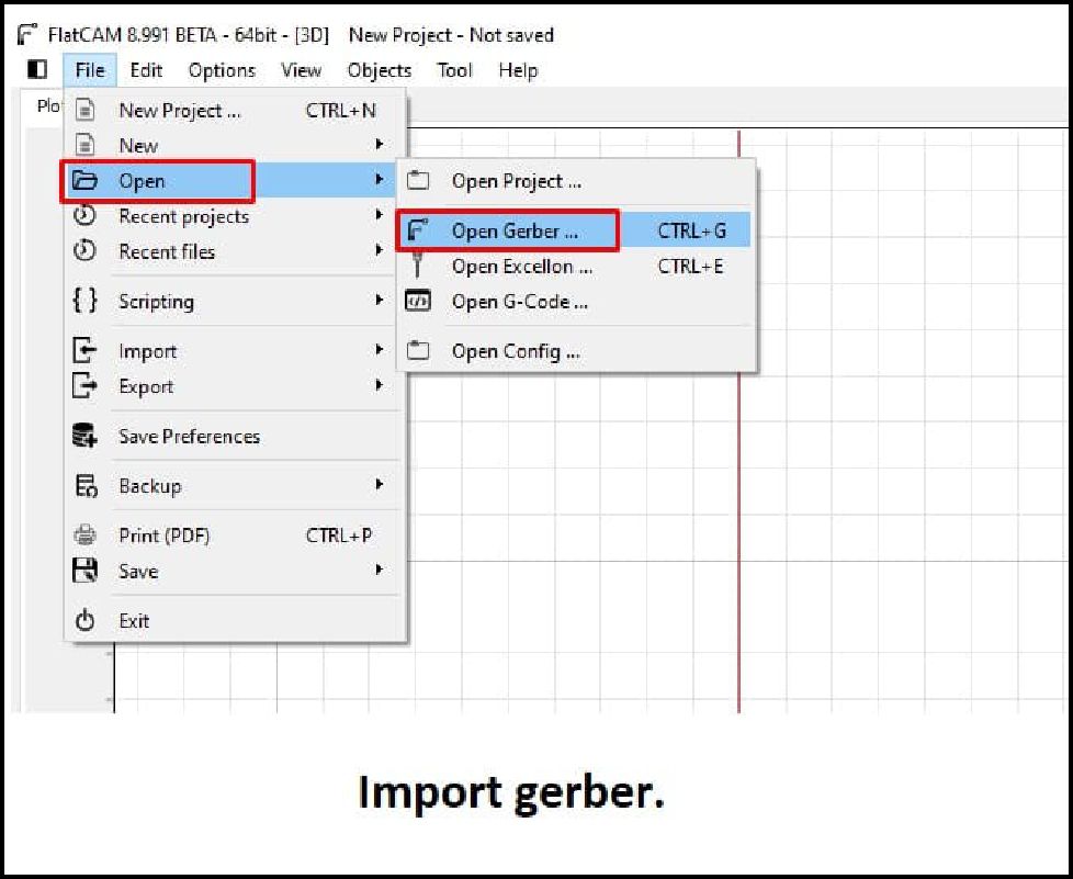
o carry out the tests with the machine, we first download the file from the example provided in class. Then, using the Flatcam software, we import the downloaded image.
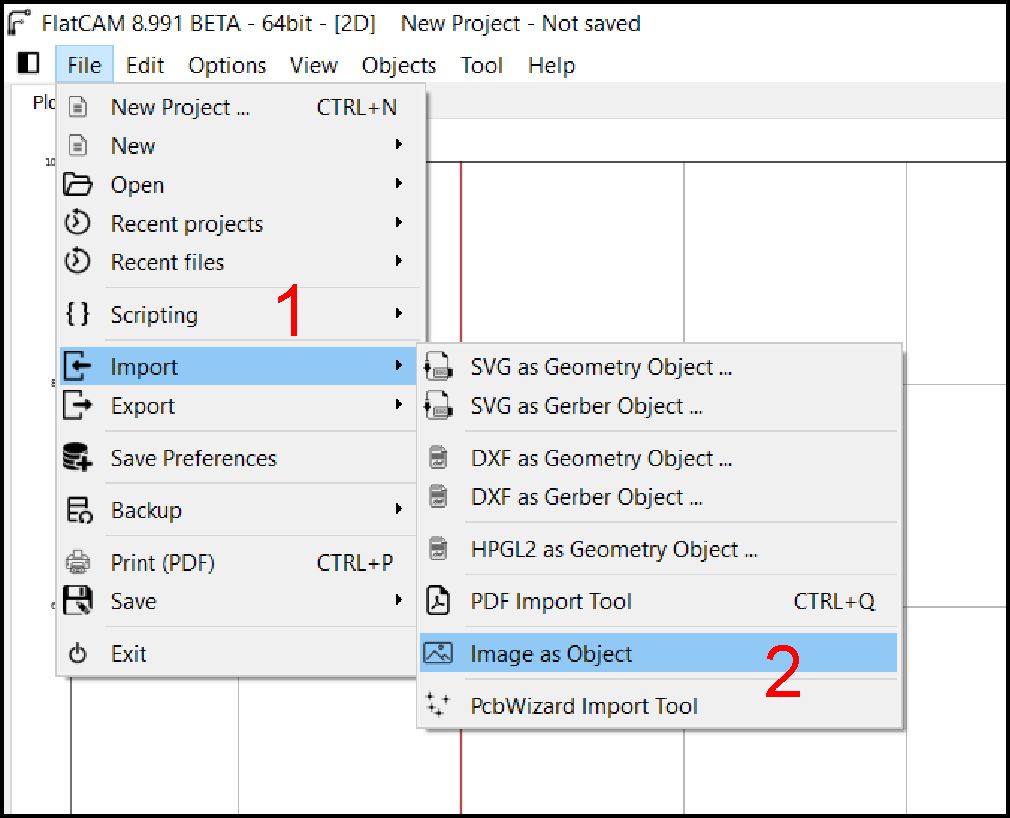
Selecting the format to import.
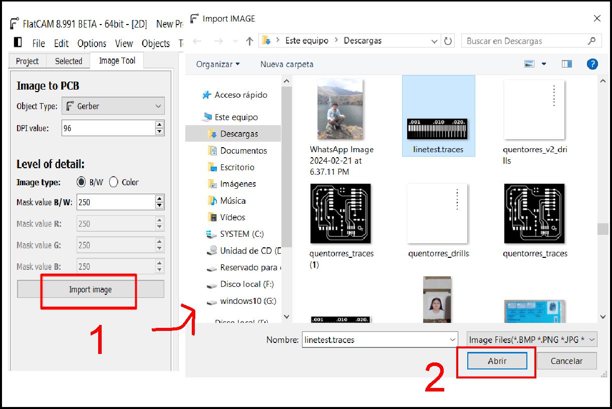
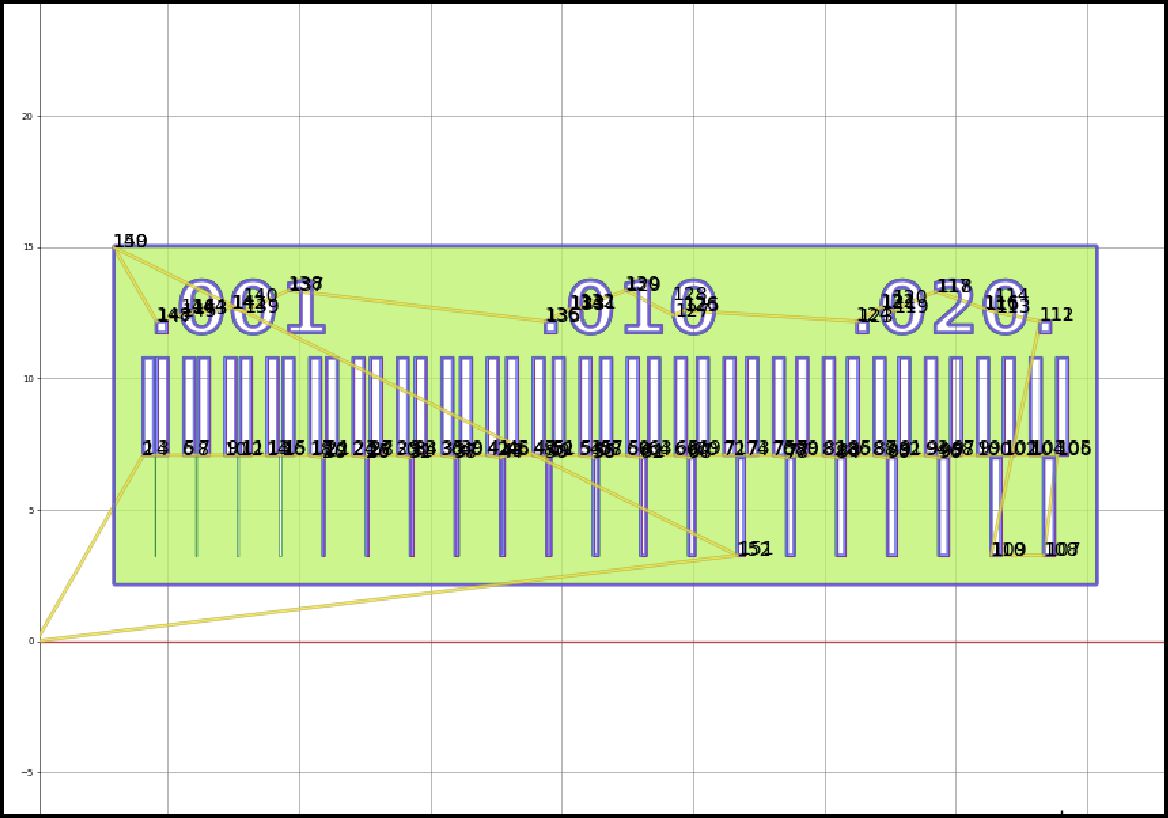
Importing downloaded image for testing.
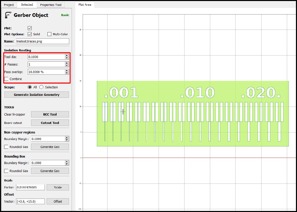
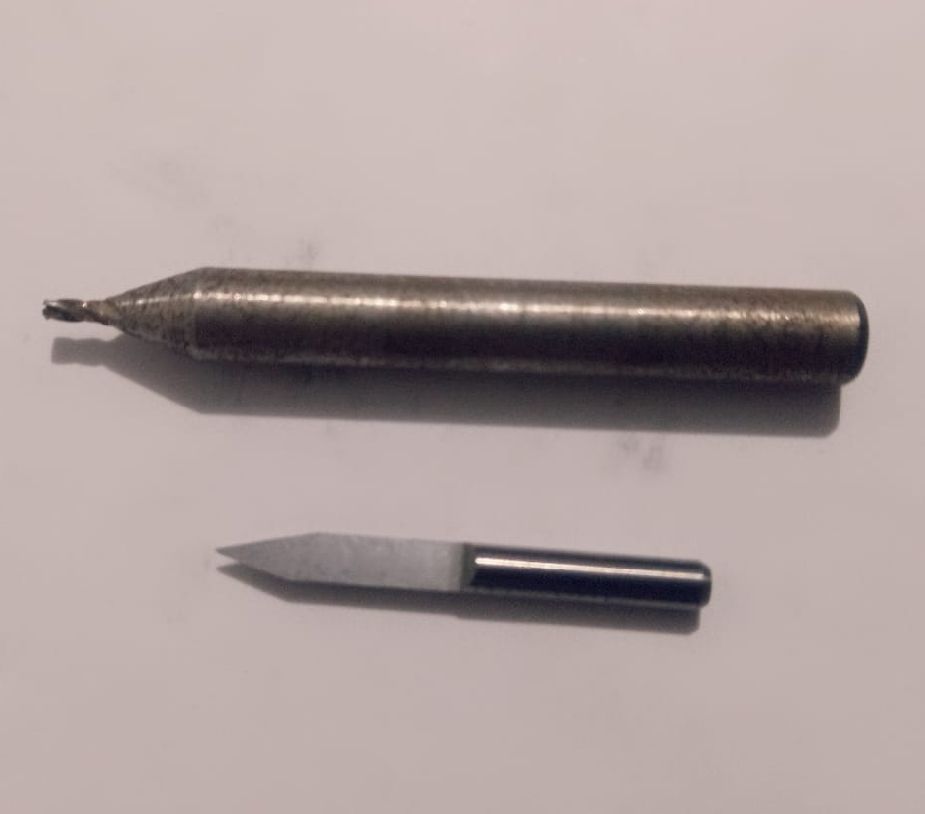
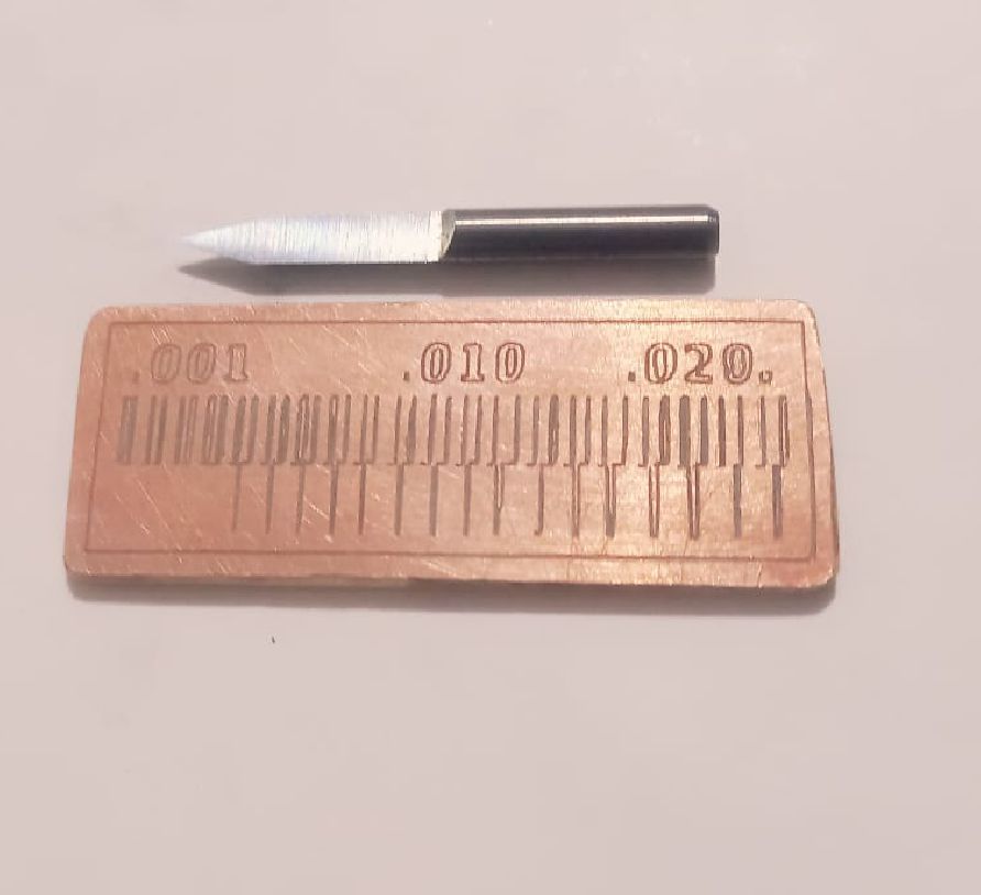
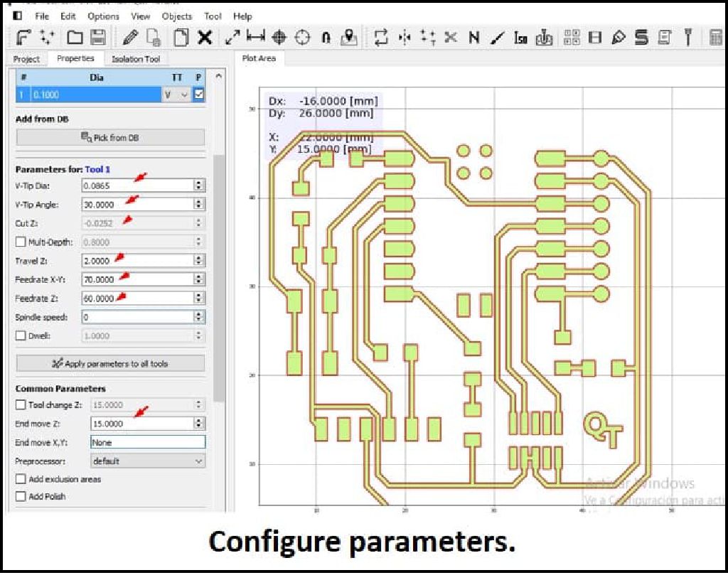
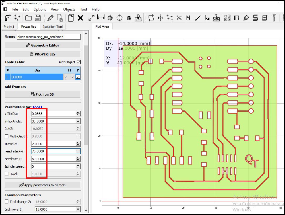
As you can see, the downloaded image was imported successfully. Next, we proceed to configure the tool, in this case, a 0.1 mm 30° "V" type milling cutter is selected.
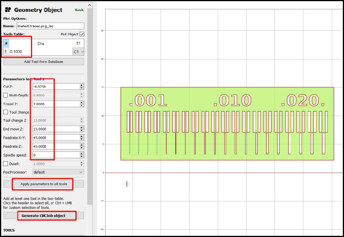
The movements in the X and Y axes are 45 steps per millimeter, while in the Z axis they are 15 steps per millimeter. We use a roughing of -0.025 mm, which is enough to remove the material in a single pass. Furthermore, when moving to another point, the movements in the Z axis are 2 mm.
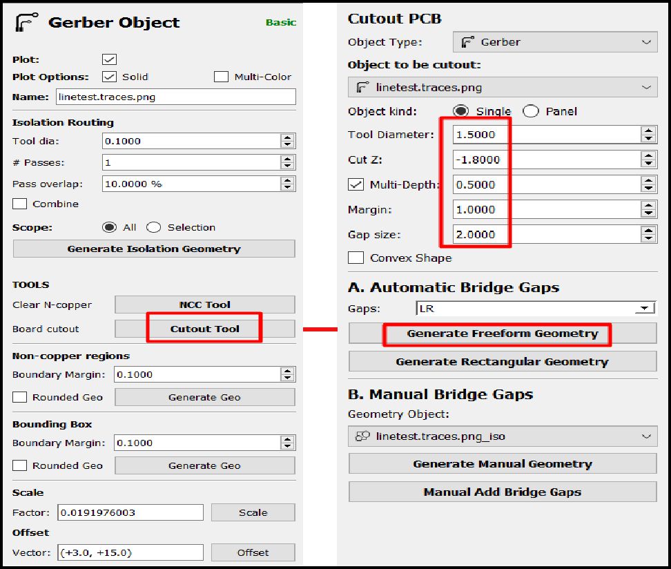
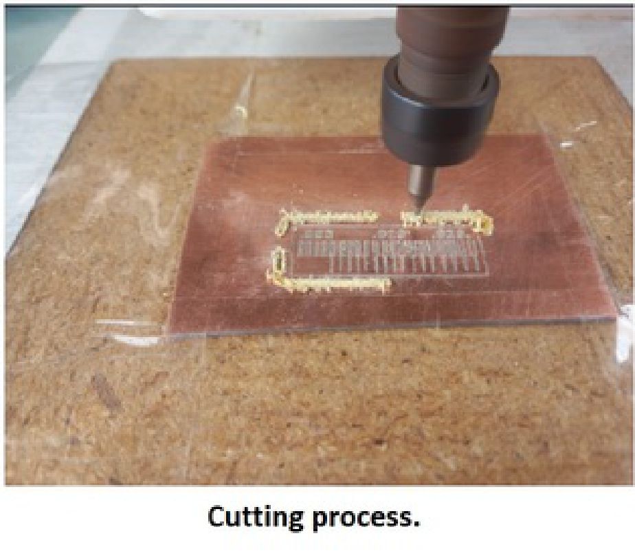
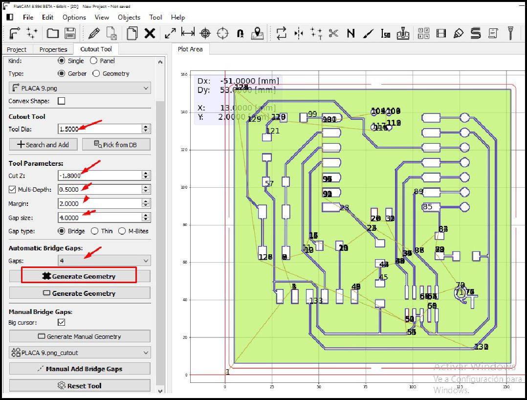
The next step is to cut the plate. To do this, we proceed to change the tool for a 4-flute type milling cutter, with a diameter of 1.5 mm. The specific parameters for this cut can be seen in the following image.
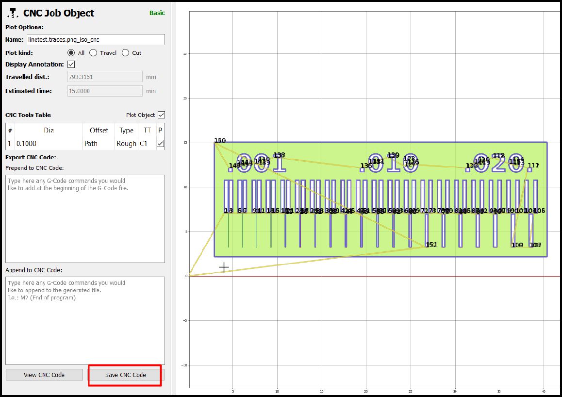
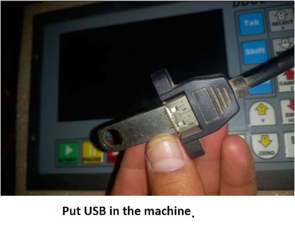
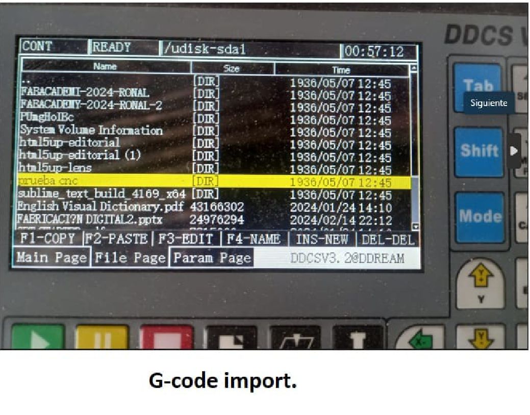
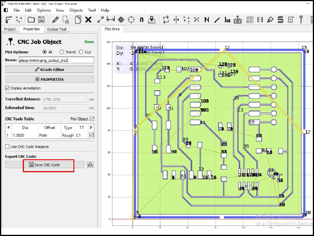
The next step is to save the generated G-code to a USB and then insert it into the machine for the process. Once on the machine, we select the file and import as shown in the following image.
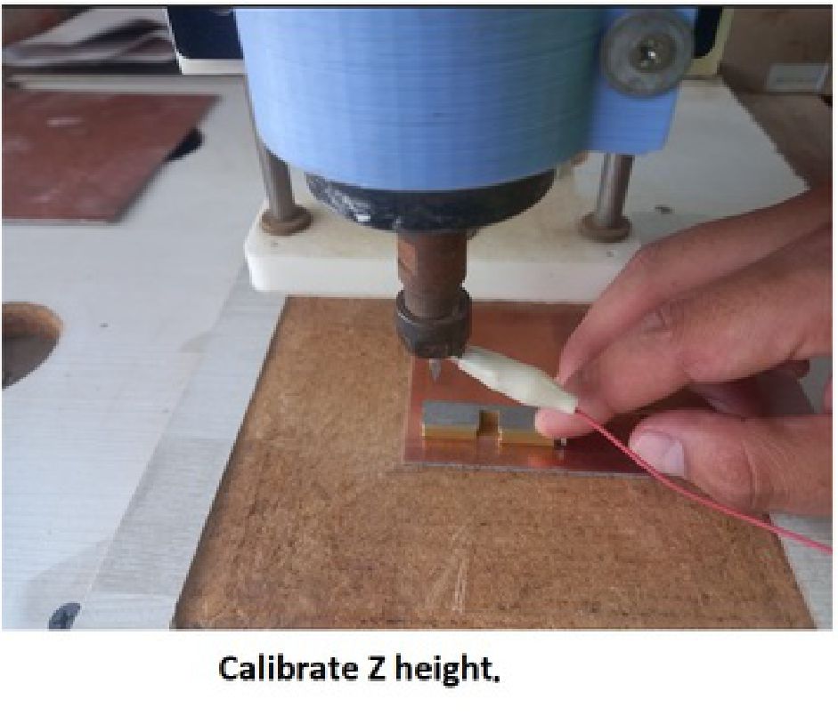
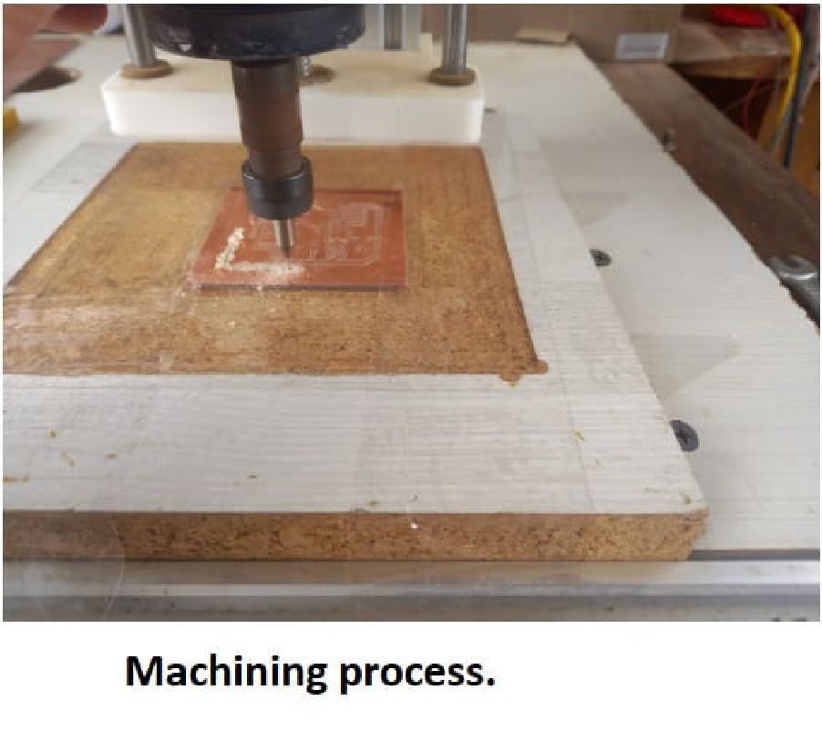
Once we have located the machine and placed the material, the next step is to calibrate the height of the tool in relation to the material. Once this calibration is completed, we proceed to start the process.
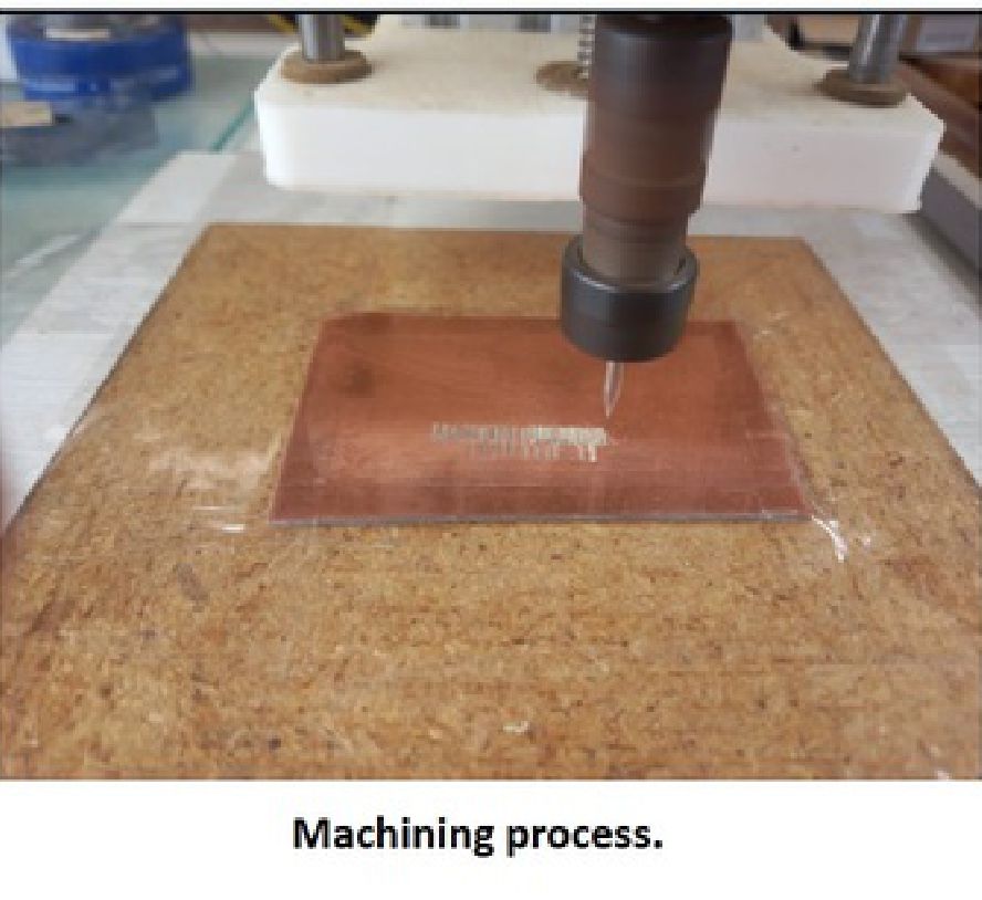
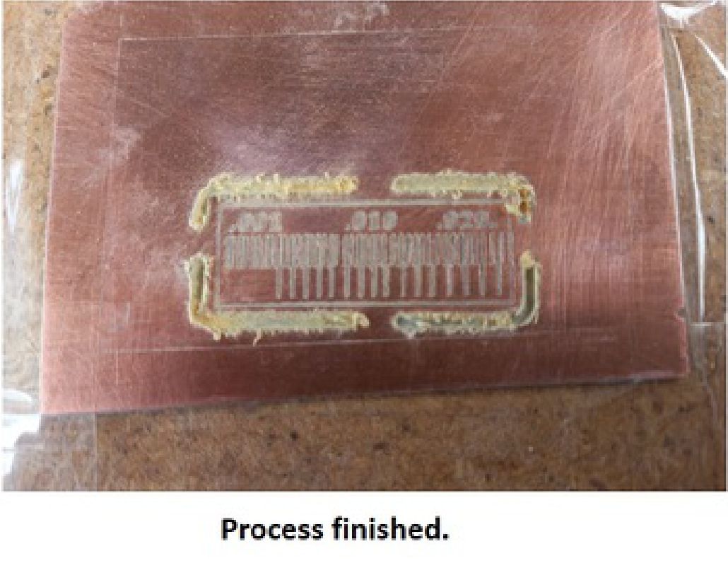
After completing the machining process, the next step is to clean the work area and make any necessary improvements. Subsequently, we prepare to carry out the next task, which is the personal assignment.
What I have learned this week is that it is crucial to calibrate the machine in terms of the travel speed in the X and Y axes. This is vital because it largely depends on the structure of your machine and, above all, the spindle. In addition, it is important to accurately adjust the material roughing level in my case to 0.025mm of Bakelite material, since if it is done too deep, there is a risk of breaking the cutter. There is also the possibility of removing or cutting some layout tracks that are too small. It has been a very profitable week, now that I understand all these parameters, I am ready to approach my individual task with confidence.
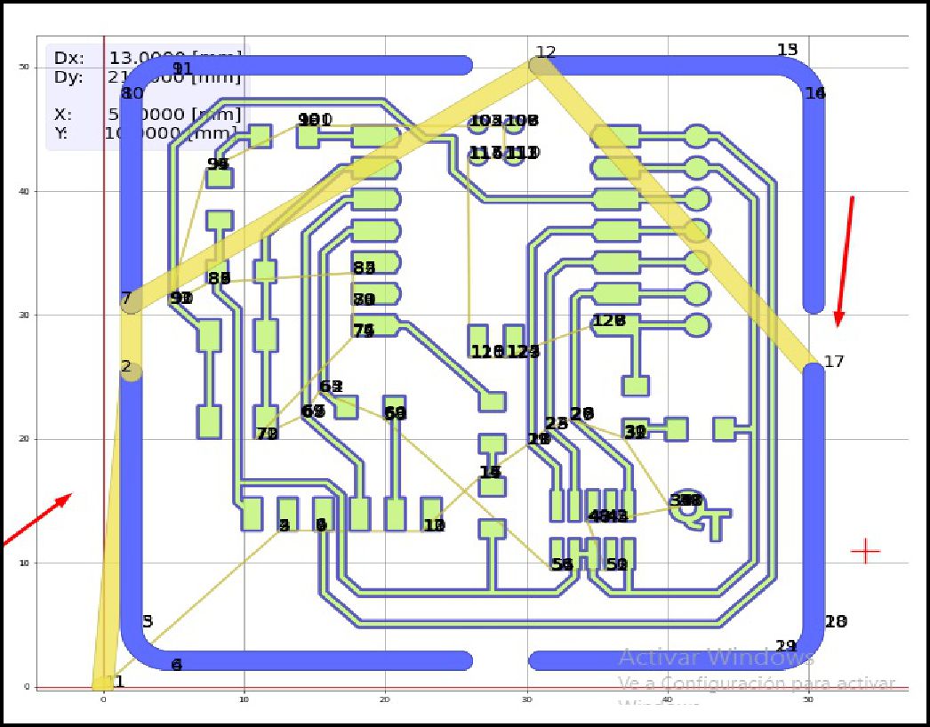
For my individual work, I started by reviewing the tutorial available in the "Electronics Production" repository by Professor Adrián Torres. After studying the documentation for it, I proceeded to download the Gerber file from the "design" version V2 folder.
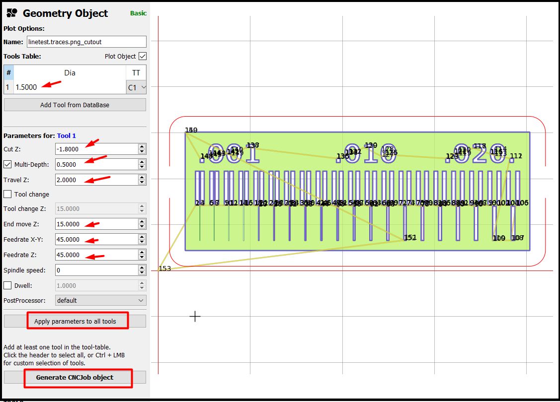
The steps to follow are as follows: Download the Gerber file, import it into Flatcam, then configure the parameters, in my case lance type milling cutter of 30 degrees at 0.1mm, "X-Y" speeds of 70mm/s, "Z" at 60mm/s. s, then click on apply parameters and the next step is click on Generate Job.
Subsequently, the configuration of the parameters of the machining process is carried out on the CNC, known as the Job process. Then, we proceed with the cutting using the 1.5 mm 4-flute bur. The next step involves transferring the file to the USB to later insert it into the CNC.
The next step is to export the G-code file generated from the tracks of the board as well as for cutting it.
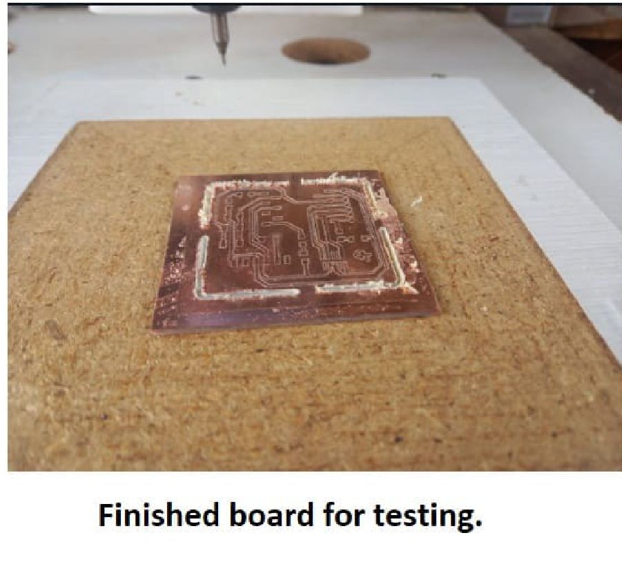
The next step involves carefully placing the Bakelite on the CNC bed and activating the board track routing process. It is crucial to ensure that the Bakelite is securely fastened to ensure optimal accuracy during routing. Once the process has started, the CNC will follow the instructions in the G-code file to sculpt the tracks according to the previously specified design.
From the process of machining the test plate, it is evident that each step requires meticulous attention. This was evident during the routing process, where an oversight when changing burs resulted in the "Z" height calibration being omitted. Unfortunately, this mistake caused irreparable damage to the plate, as the cutting burr completely destroyed it. This highlights the importance of maintaining focus and precision at every stage of the process to avoid costly setbacks.

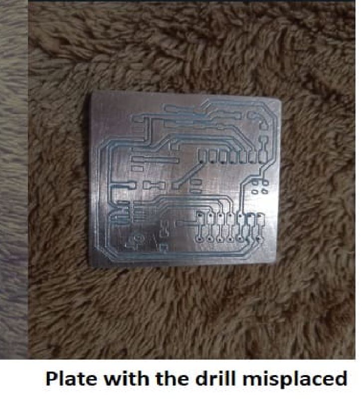
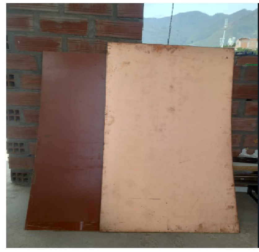
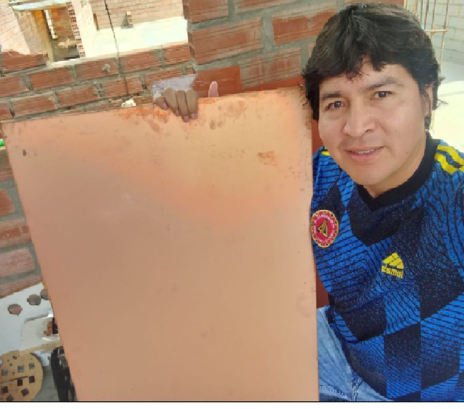
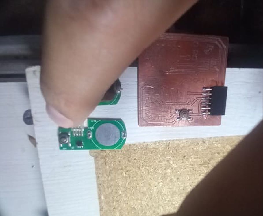
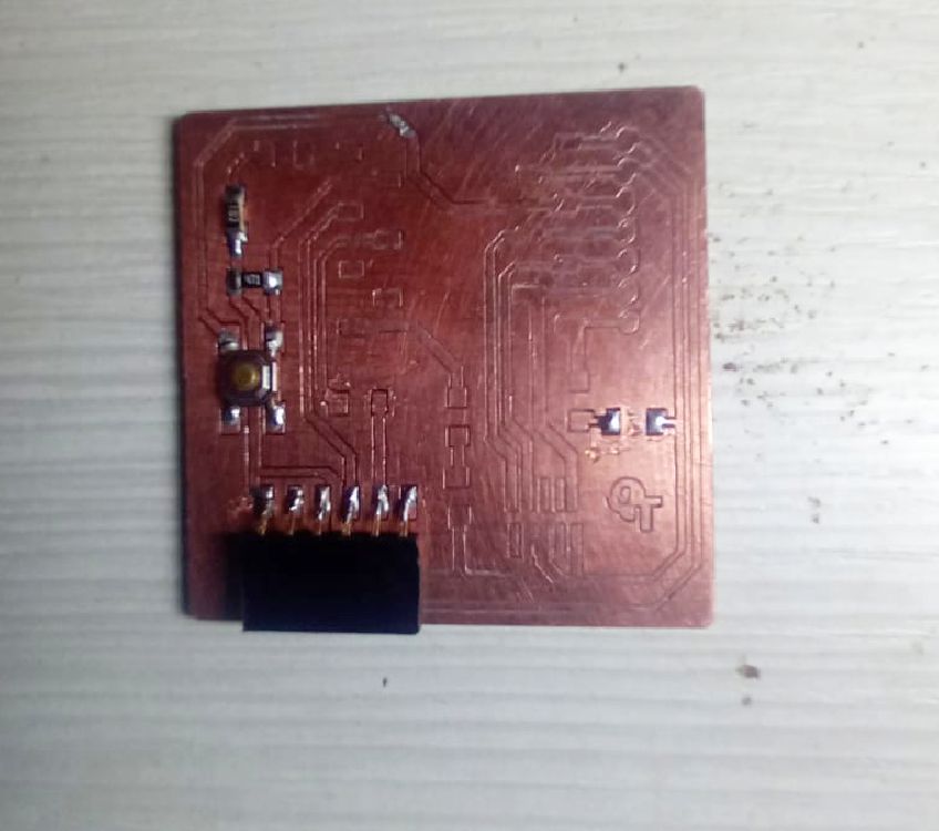
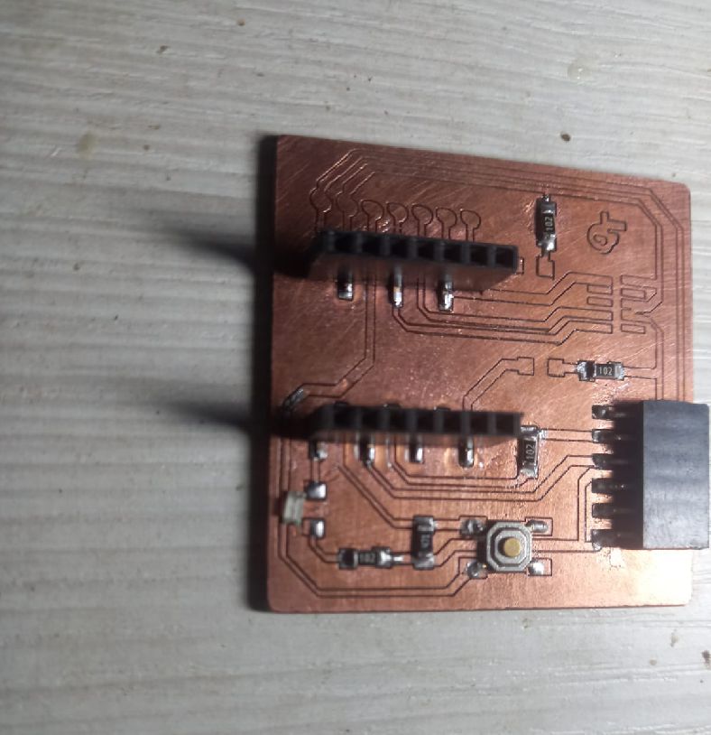
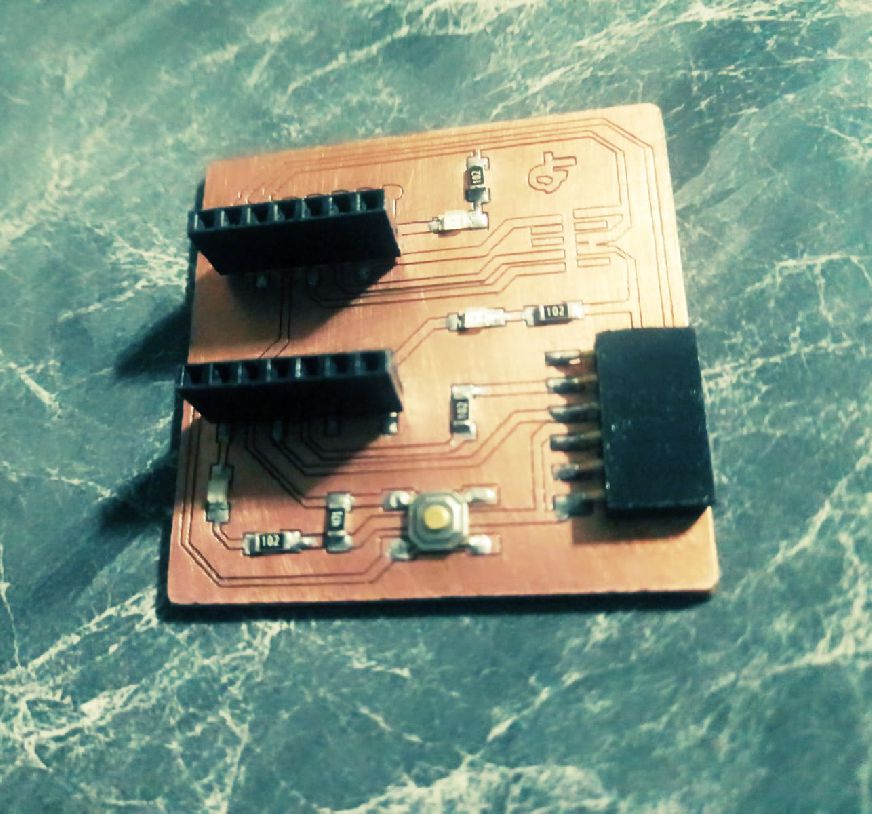
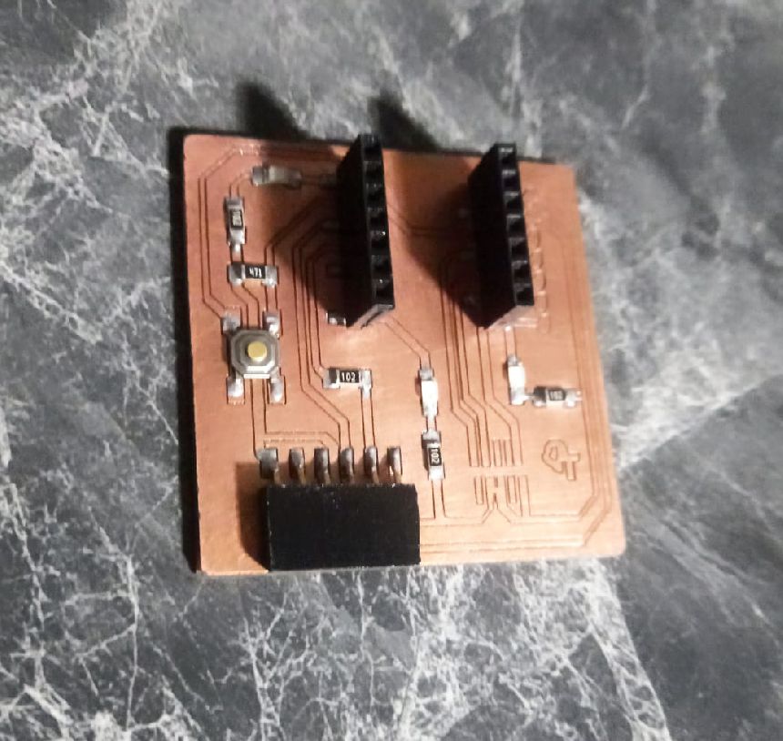
Now I present several plates that I have made in an attempt to improve my work, however, it is evident that there is still a way to go before reaching perfection.

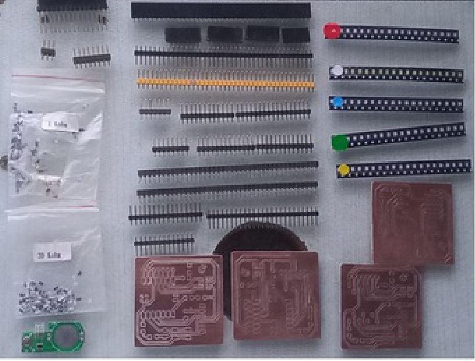
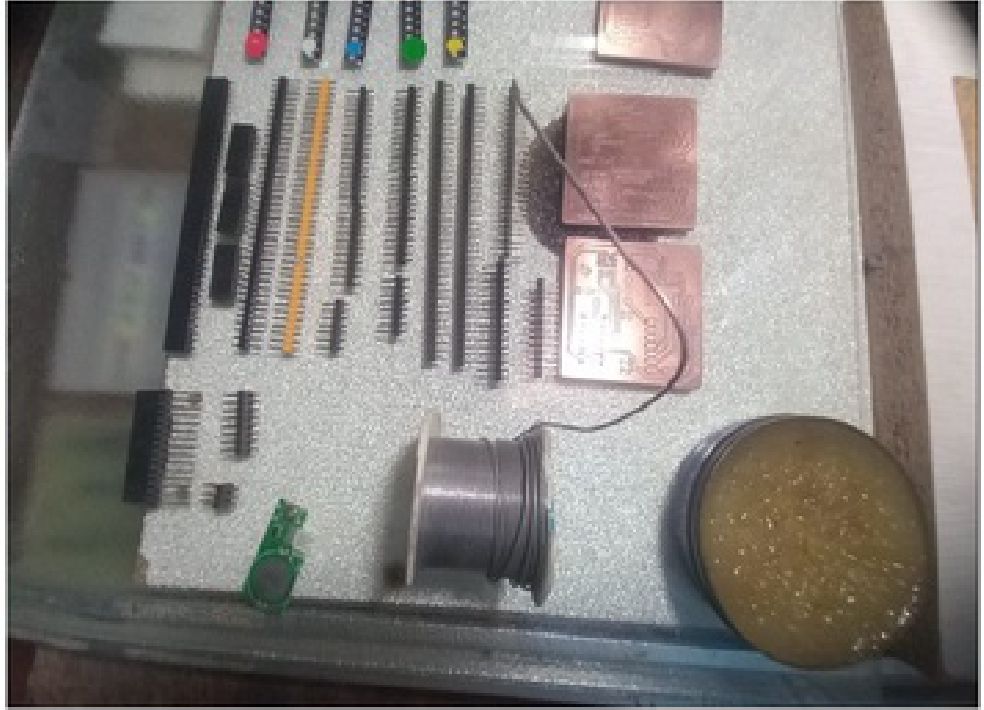
"Now, the next step involves the process of soldering the electronic components according to the list provided in "Electronics Production". It is crucial to ensure that you have all the necessary components as well as the tools to be able to carry out the individual job safely. effective."
The welding process can be complicated, but with care and attention, it can be carried out without a hitch. However, it is important to note that soldering surface mount (SMD) components requires patience and additional practice due to its delicate and precise nature.
All components were purchased in advance, except for the Xiao, whose arrival on time to complete the assigned task was possible thanks to the efficient management of our mentors at Fab Lab Perú, in particular, the outstanding work of teacher Vaneza, who was who sent us from the United States.
Unfortunately, I couldn't find the button component in nearby electronic stores. However, I managed to solve this problem by recycling buttons from an unused circuit.
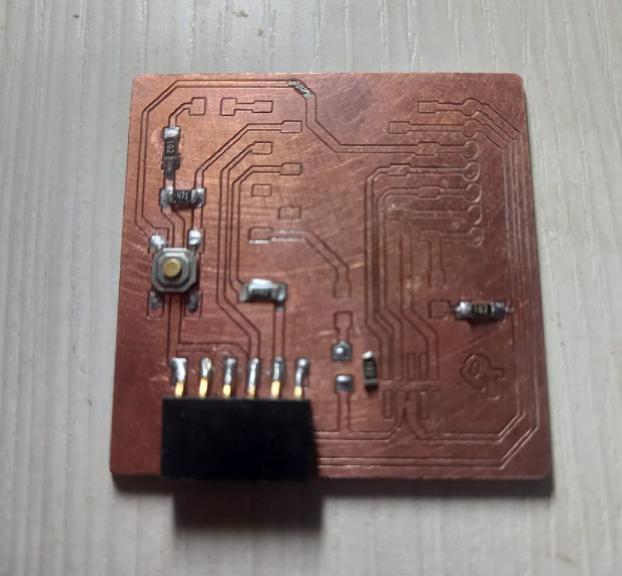
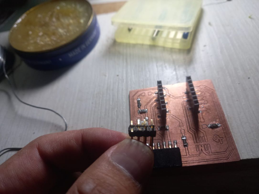
The soldering process was carried out as follows: First, I applied flux over the areas where the components would be soldered. I then applied a small amount of tin to these areas, making sure not to warp the flat surface required for each part. Afterwards, I placed each component in its designated place and used a soldering iron (in my case, 30W to 70W) to solder it. During this process, I only added more solder when necessary to ensure proper soldering of the component. This procedure was repeated iteratively until the last component was soldered.
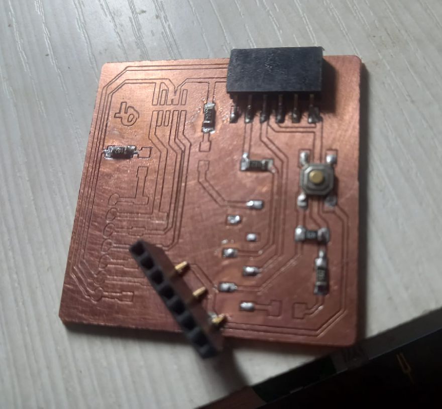
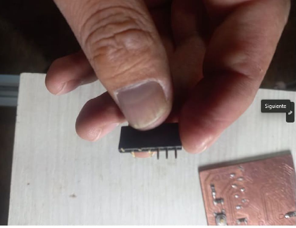
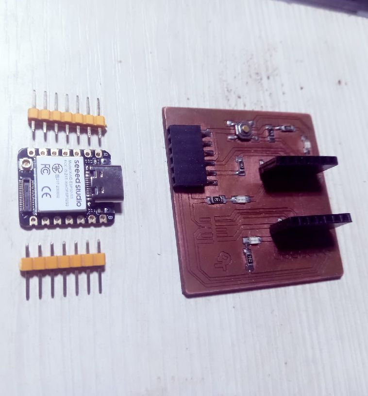
The next step was to solder the pins of the XIAO ESP32-C3 so that it could be placed on the finished board. This allowed us to carry out the first tests of the circuit.
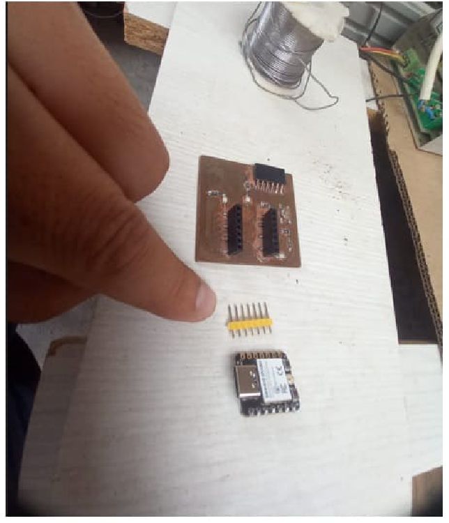
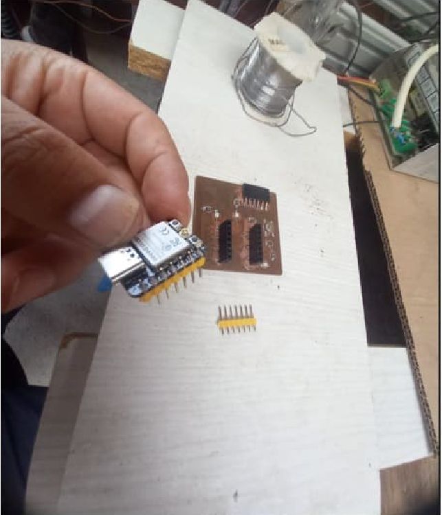
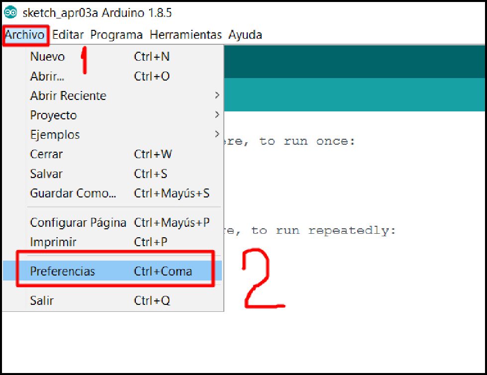
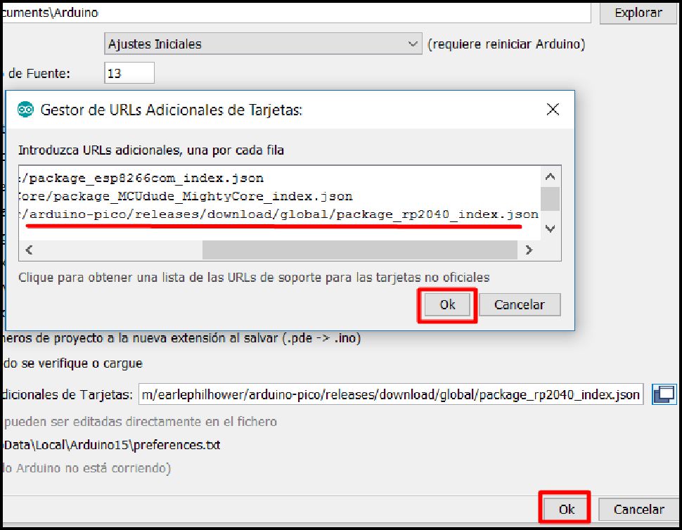
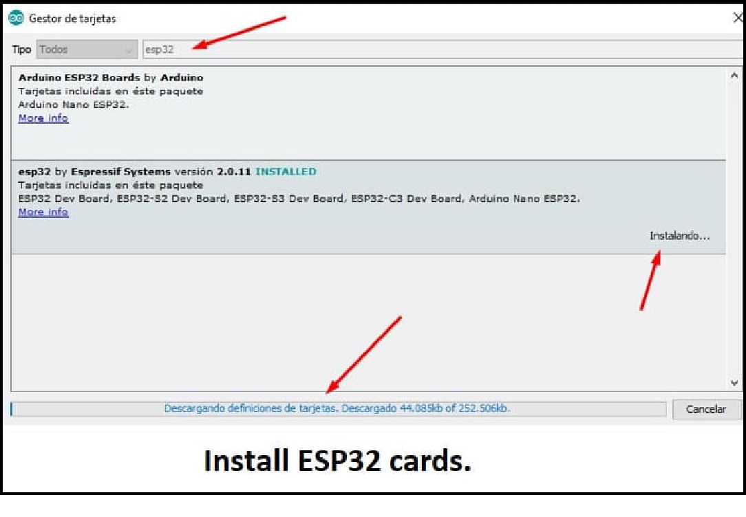
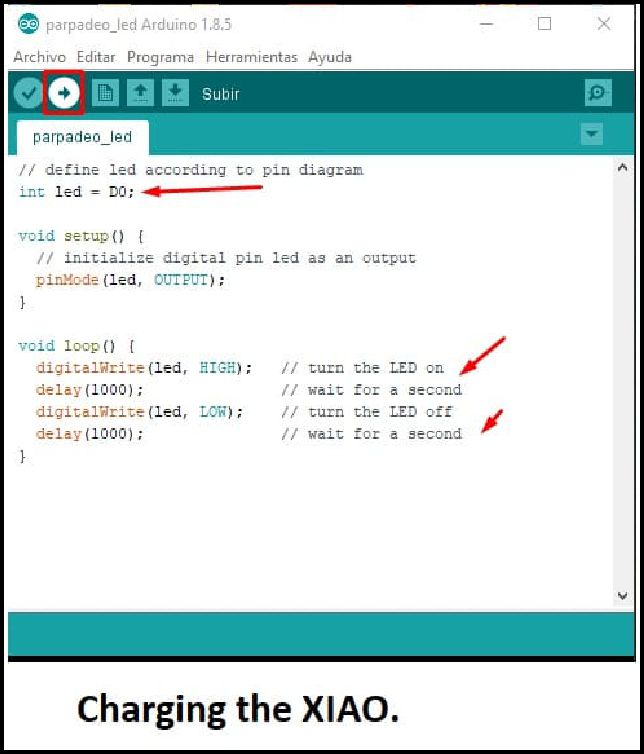
To carry out the process of loading a code and putting the XIAO into operation, we begin by installing the necessary boards as shown in the following images.
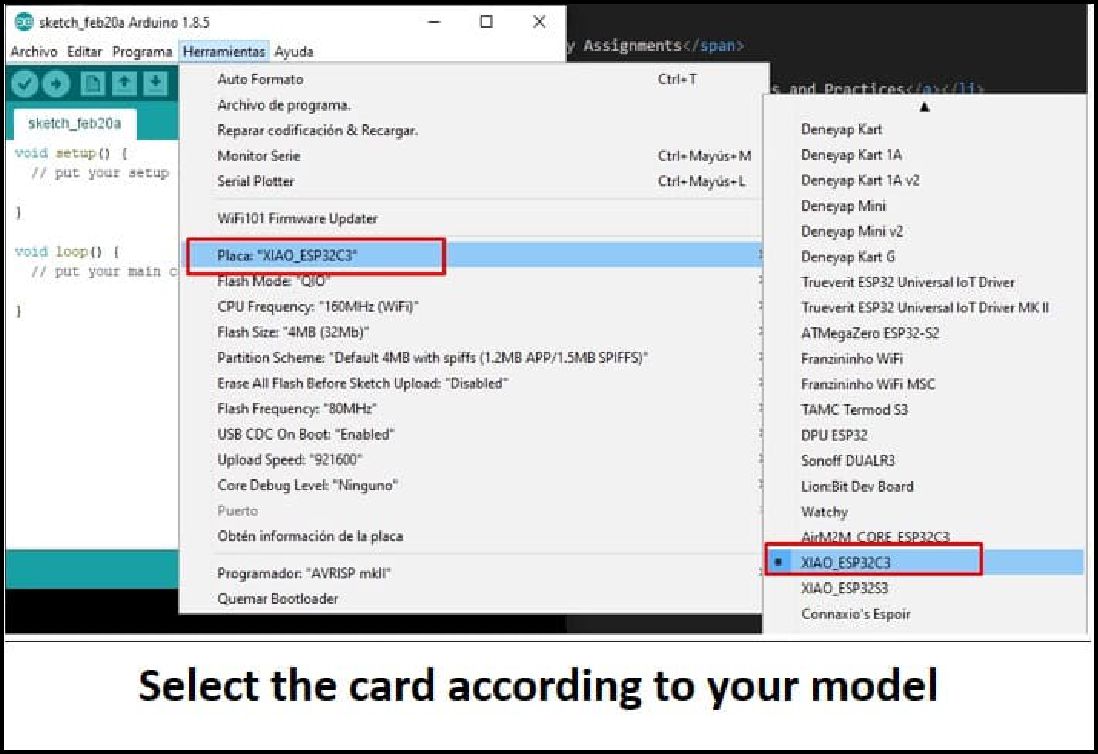
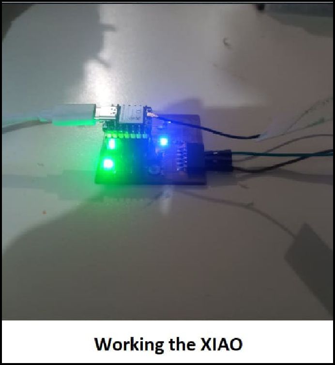
The next step involves selecting the card corresponding to our model in the toolbar. Then, we go to the 'Tools' menu and access the card manager to select 'XIAO ESP32-C3'. Once this is completed, we proceed to load a short code that flashes an LED every second. With these steps, your XIAO will be up and running correctly.
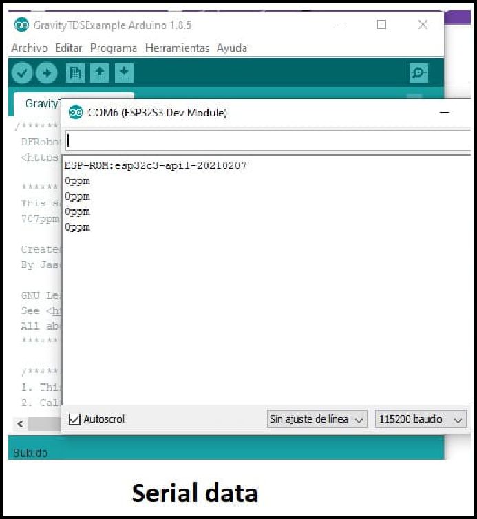
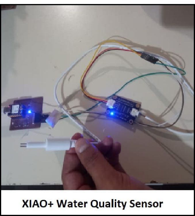
The second test was carried out by connecting a TDS water quality sensor and viewing the parameters through the serial monitor. Of course, this process is still in the testing phase for my final project.
In short, this project not only involves technical skills, but also patience, attention to detail, and a careful approach to every step of the process. With proper planning and precise execution, satisfactory results can be achieved in electronic production with a CNC router and the XIAO ESP32-C3 microcontroller. Be patient since our first job with the CNC will not turn out perfect, with perseverance and practice it will turn out excellent.
Development of custom electronic boards with CNC Router.
Development of personalized keychains and ornaments with CNC Laser.
Development of custom machines "Desktop CNC Laser.

Huánuco is a Peruvian city, capital of the district, province and department of the same name in the north-central area of the country. The city has a population of 235,529 inhabitants. .